Detailed Product Description
Part number : E3623-721-0A0
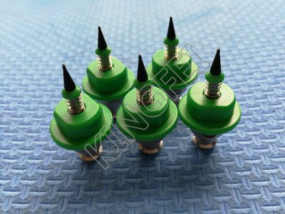
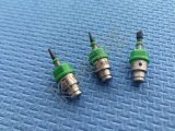
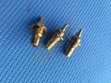
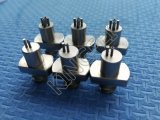
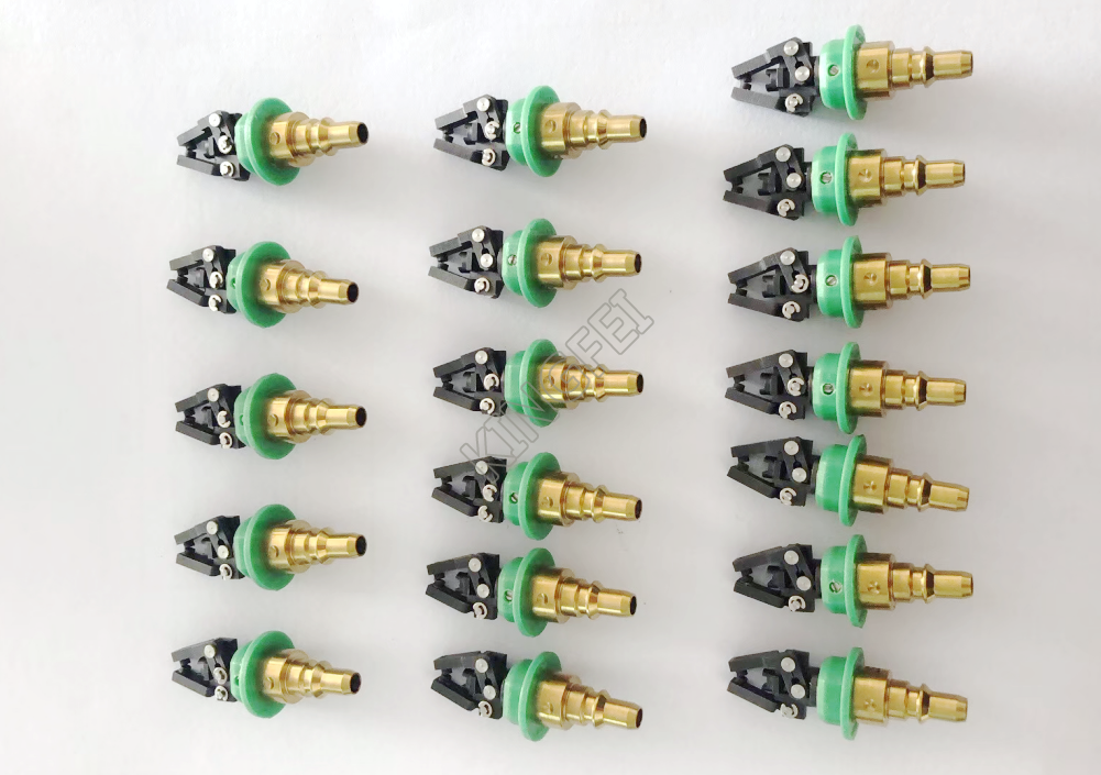
Description : JUKI gripper nozzle 800 ASSY for 0.8mm-2.2mm
Part number : E3624-721-0A0
Description : JUKI gripper nozzle 801 ASSY for 1.8mm-3.2mm
Part number : E3625-721-0A0
Description : JUKI gripper nozzle 802 ASSY for 2.8mm-4.2mm
Part number : E3626-721-0A0
Description : JUKI gripper nozzle 803 ASSY for 3.8mm-5.2mm
Part number : E3627-721-0A0
Description : JUKI gripper nozzle 804 ASSY
Gripper Nozzle Data:
This is the item only for a gripper nozzle
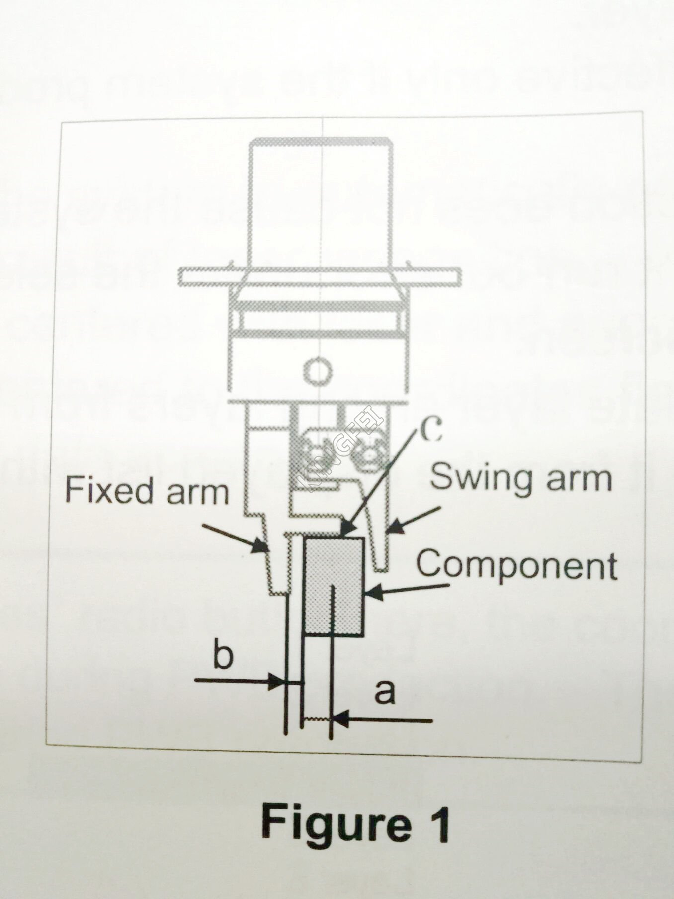
1, Grip position: Enter a negative value ("-a")into the "Y" field as the offset from the center of a component to the side against which a component is pused ("a" of Figure 1). Do not enter any value other than "0" into the "X" field.
2, Horizontal clearance: Enter a negative value ("b") as the clearance between the side against which the arm on the gripper nozzle fixed side is pushed and a component("b" of figure 1). Note that the movement direction varies depending on the nozzle type and/ or nozzle direction. Usually, set the default value that is automatically input.
3, Nozzle direction at picking: Specify the nozzle direction when the nozzle picks up a component that is supplied at 0 degrees. Specify one of the directions: 0.90, 180 and 270 degrees/
4, Height adjustment: Enter the component pick-ip height offset value( gap between c and the top side of a component. Normally, set "-0.5 mm" to keep a component horizontal.
Setting items when a gripper nozzle is used:
In addition to the items described above, you have to set the following items for a gripper nozzle in the different way from those for other nozzles.
1, When you use a new gripper nozzle, select the <file>/<Read Nzl. data> commands on the " machine setup" menu to load the information on the gripper nozzle from a floppy disk first.
2, Set the nozzle onto the ATC. Attach the gripper nozzle onto the ATC so that the fixed arm of the gripper nozzle can be located on the rear and the swing arm can be located on the front with viewing the ATC unit from the front.
3, Specify the component data.
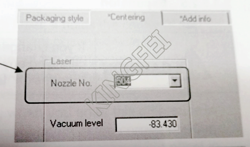
a, set the nozzle number.
The numbers for gripper nozzles are from 800 to 809.
b, Set the laser position. ( This setting is required for both LNC60 and FMLA.) Specify the distance from the tip of the fixed arm to the laser position. Guideline for setting the " Laser position": (COmponent height-3.5mm*)/2. Make fine adjustments with based on the lead position.
* Distance from the "C" shown in figure 1 to the fixed arm=3.5 mm Example: When the component height is 5mm(5-3.50/2 = -0/75 mm
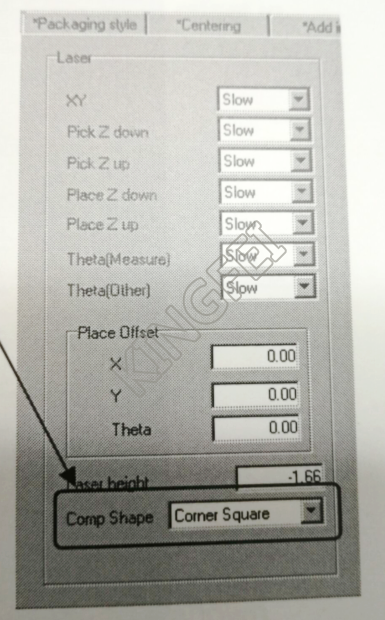
4, Set the pick data. Perform the teaching operation for "X" and " Y" in the normal way. A value in the " Z" field is automatically calculated based on the information on the nozzle and component height registered on the "Machine setup" menu. You do not have to teach this coordinate.
Contact Details
Dongguan KingFei Technology Co.,Limited
Contact Person: Sandy