


Common use electronic components
Jun 30, 2020 Editor: admin
For engineers engaged in the electronics industry, electronic components everyday will be used, but in fact, many engineers may not know the doors inside. Here is a list of the top ten electronic components commonly used by engineers, as well as related basic concepts and knowledge, and review them with you.
I. Resistance.
As workers in the electronics industry, resistors are known to everyone. There is no doubt about its importance. People say, "Resistors are the most widely used components in all electronic circuits."
As workers in the electronics industry, resistors are known to everyone. There is no doubt about its importance. People say, "Resistors are the most widely used components in all electronic circuits."

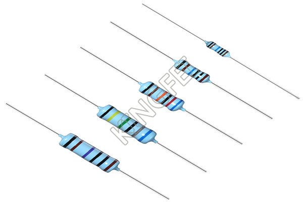
Resistance, because of the blocking effect of the substance on the current, so it is called the resistive material under this action. Resistance will lead to changes in electron flux, the smaller the resistance, the greater the electron flux, and vice versa. A substance with no resistance or very low resistance is called an electrical conductor, or conductor for short. The substance that cannot form current transmission is called electrical insulator, which is referred to as insulator for short.
In physics, the resistance (Resistance) is used to represent the blocking effect of the conductor on the current. The greater the resistance of the conductor, the greater the blocking effect of the conductor on the current. The resistance is generally different for different conductors, and the resistance is a characteristic of the conductor itself. Resistive elements are energy-consuming elements that hinder the current.
The resistance value of the resistance element is generally related to the temperature. The physical quantity to measure the resistance affected by the temperature is the temperature coefficient, which is defined as the percentage of the resistance value changing when the temperature increases by 1 ℃.
Resistors are represented by "R" plus numbers in the circuit, for example, R1 represents the resistance numbered 1. The main functions of resistors in the circuit are shunt, current limiting, voltage division, bias and so on.
II, capacitance.
Capacitance (or capacitance, Capacitance)) refers to the amount of charge stored at a given potential difference; marked as C, the international unit is Farah (F). Generally speaking, the electric charge will move under the force in the electric field, and when there is a medium between the conductors, it hinders the movement of the electric charge and causes the charge to accumulate on the conductor; the most common example of the cumulative storage of electric charge is two parallel metal plates. It is also a common name for capacitors.
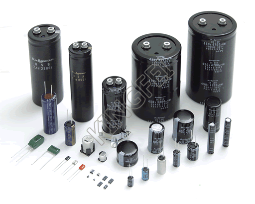

1. The capacitance in the circuit is generally represented by "C" plus a number (for example, C13 represents the capacitor numbered 13). Capacitance is a component composed of two metal films close to each other and separated by insulating materials in the middle. The main characteristic of capacitance is DC AC. The capacity of capacitance represents the amount of electric energy that can be stored. The blocking effect of capacitance on AC signal is called capacitance reactance, which is related to the frequency and capacitance of AC signal. Capacitance XC=1/ 2 π FC (f represents the frequency of AC signal, C represents capacitance) the types of capacitors commonly used in telephones are electrolytic capacitors, ceramic chip capacitors, patch capacitors, monolithic capacitors, tantalum capacitors and polyester capacitors.
2. Identification method: the identification method of capacitance is basically the same as that of resistance, which can be divided into three kinds: straight standard method, color standard method and digital scale method. The basic unit of capacitance is expressed by Farah (F), and other units are: millimethod (mF), micro method (uF), nano method (nF), skin method (pF).
2. Identification method: the identification method of capacitance is basically the same as that of resistance, which can be divided into three kinds: straight standard method, color standard method and digital scale method. The basic unit of capacitance is expressed by Farah (F), and other units are: millimethod (mF), micro method (uF), nano method (nF), skin method (pF).
III, Crystal diodes.
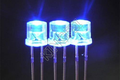

A semiconductor device at both ends of a (crystaldiode) solid-state electronic device. The main feature of these devices is that they have nonlinear current-voltage characteristics. Since then, with the development of semiconductor materials and technology, a variety of crystal diodes with various structures and functions have been developed by using different semiconductor materials, doping distribution and geometric structure. Manufacturing materials include germanium, silicon and compound semiconductors. Crystal diodes can be used to generate, control, receive, transform, amplify signals and convert energy.
Crystal diodes are often represented by "D" plus numbers in the circuit, for example: D5 represents the diode numbered 5.
1. Function: the main characteristic of the diode is unidirectional conductivity, that is, under the action of forward voltage, the on resistance is very small, while under the action of reverse voltage, the on resistance is maximum or infinite. Because of the above characteristics, diodes are often used in rectification, isolation, voltage stabilization, polarity protection, coding control, FM modulation and noise suppression circuits in cordless telephones. The crystal diodes used in telephones can be divided into rectifier diodes (such as 1N4004), isolation diodes (such as 1N4148), Schottky diodes (such as BAT85), light emitting diodes, voltage regulator diodes and so on.
2. Identification method: the identification of the diode is very simple. The N pole (negative pole) of the low power diode is mostly marked by a color circle on the outside of the diode. Some diodes also use the special symbol of the diode to represent the P pole (positive pole) or N pole (negative pole). There are also symbols marked as "P" and "N" to determine the polarity of the diode. The positive and negative electrodes of light-emitting diodes can be identified by the length of the pins. The long feet are positive and the short feet are negative.
3. Points for attention in testing: when using a digital multimeter to measure the diode, the red meter connects the positive pole of the diode and the black meter connects the negative pole of the diode. At this time, the measured resistance value is the positive conduction resistance value of the diode, which is opposite to the pen connection method of the pointer multimeter.
IV. Voltage stabilizing diodes.
Zener diodes (also known as Zener diodes) are semiconductor devices that have high resistance up to the critical reverse breakdown voltage. Voltage regulator diodes are often represented by "ZD" plus numbers in the circuit, such as: ZD5 represents the voltage regulator tube numbered 5.

1. The voltage-stabilizing principle of Zener diodes: the characteristic of Zener diodes is that after breakdown, the voltage at both ends of the diodes remains basically unchanged. In this way, when the regulator is connected to the circuit, if the voltage of the power supply fluctuates or the voltage of each point in the circuit changes due to other reasons, the voltage at both ends of the load will remain basically unchanged.
2. Fault characteristics: the faults of Zener diodes are mainly manifested in open circuit, short circuit and unstable voltage regulation. Among the three faults, the former fault shows the increase of power supply voltage, and the latter two faults show that the power supply voltage becomes low to zero volt or the output is unstable.
2. Fault characteristics: the faults of Zener diodes are mainly manifested in open circuit, short circuit and unstable voltage regulation. Among the three faults, the former fault shows the increase of power supply voltage, and the latter two faults show that the power supply voltage becomes low to zero volt or the output is unstable.
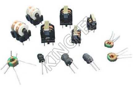
Inductance.
Inductance: when the coil passes through the current, a magnetic field induction is formed in the coil, and the induced magnetic field produces an induced current to resist the current passing through the coil. We call this interaction between the current and the coil the inductance, or inductance, in "Henry" (H). This property can also be used to make inductors.
Inductors are often represented by "L" plus numbers in the circuit, such as: L6 represents the inductor numbered 6. The inductance coil is made of insulated wires wound around a certain number of turns on the insulated skeleton. DC can pass through the coil, and the DC resistance is the resistance of the wire itself, and the voltage drop is very small; when the AC signal passes through the coil, there will be a self-inductive EMF at both ends of the coil, and the direction of the self-inductive EMF is opposite to that of the applied voltage, hindering the passage of AC, so the characteristic of the inductor is DC resistance, and the higher the frequency, the greater the coil impedance. The inductor can form an oscillating circuit with the capacitor in the circuit. Inductors generally have straight standard method and color standard method, and color standard method is similar to resistance. For example, brown, black, gold and gold represent inductors of 1uH (error 5%).
The basic unit of inductor is: Heng (H) conversion unit: 1H=103mH=106uH.
VI. Varactor diode.
Varactor (Varactor Diodes) is also called variable reactance diode. It is a kind of diode made by using the dependence and principle of PN junction capacitance (barrier capacitance) and its reverse bias voltage Vr.
The tube varactor is a kind of special diode specially designed according to the principle that the junction capacitance of the "PN junction" inside the ordinary diode changes with the change of the applied reverse voltage. The varactor is mainly used in the high frequency modulation circuit of the mobile phone or landline in the cordless telephone to modulate the low frequency signal to the high frequency signal and transmit it. In the working state, the varactor modulation voltage is generally added to the negative electrode, so that the internal junction capacitance of the varactor varies with the modulation voltage.
The fault of the varactor diode is mainly manifested as leakage or poor performance: (1) when leakage occurs, the high-frequency modulation circuit will not work or the modulation performance will become worse. (2) when the capacitive performance becomes worse, the operation of the high-frequency modulation circuit is unstable, so that the modulated high-frequency signal is distorted after being sent to the other party and received by the other party. When one of the above occurs, the varactor of the same type should be replaced.
VII, Crystal Triode.
Transistor is one of the basic components of semiconductors, which has the function of current amplification and is the core component of electronic circuits. The transistor makes two PN junctions close to each other on a semiconductor substrate. The two PN junctions divide the positive semiconductor into three parts, the middle part is the base region, and the two sides are emitting region and collector region. There are two kinds of arrangement: PNP and NPN.
Crystal transistors are often represented by "Q" plus numbers in the circuit, such as: Q17 represents the transistor numbered 17.
1. Features: the crystal transistor (referred to as the transistor) is a special device with two PN junctions inside and with the ability to amplify. It can be divided into two types: NPN type and PNP type. These two types of transistors can complement each other in terms of working characteristics. The pair transistors in the so-called OTL circuit are paired with PNP type and NPN type. PNP transistors commonly used in telephones are: A92, 9015 and other models; NPN transistors are: A42, 9014, 9018, 9013, 9012 and other models.
2. The crystal transistor is mainly used to amplify in the amplifying circuit, and there are three kinds of connection methods in the common circuit.
VIII, Field effect transistors.
(Field Effect Transistor is abbreviated as (FET)) for FET. Many carriers participate in conducting electricity, also known as monopole transistors. It belongs to voltage-controlled semiconductor device. With the advantages of high input resistance, low noise, low power consumption, large dynamic range, easy integration, no secondary breakdown, wide safe working area and so on, it has become a strong competitor of bipolar transistors and power transistors.
The main results are as follows: 1. field effect transistor has the advantages of high input impedance and low noise, so it is also widely used in all kinds of electronic devices. In particular, using the field effect transistor as the input stage of the whole electronic equipment, we can obtain the performance that the general transistor is difficult to achieve.
2. FETs can be divided into two types: junction type and insulated gate type, and their control principles are the same.
3. Comparison between FET and transistor.
The main results are as follows: (1) the FET is the voltage control element, while the transistor is the current control element. When only a small amount of current from the signal source is allowed, the field effect transistor should be selected, while under the condition that the signal voltage is low and more current is allowed from the signal source, the transistor should be selected.
(2) FETs conduct electricity by using most carriers, so it is called monopole device, while transistors not only have many carriers, but also use minority carriers to conduct electricity. It is called bipolar device.
(3) the source and drain of some FETs can be used interchangeably, the gate voltage can also be positive or negative, and the flexibility is better than that of transistors.
(4) FETs can work under the conditions of very low current and low voltage, and its manufacturing process can easily integrate many FETs on a silicon wafer, so FETs have been widely used in large-scale integrated circuits.
IX. Sensor.

A sensor is a physical device or biological organ that can detect and sense external signals, physical conditions (such as light, heat, humidity) or chemical composition (such as smoke), and transmit the detected information to other devices or organs.
The national standard GB7665-87 defines the sensor as "a device or device that can sense the measured parts and convert them into available signals according to certain rules, which is usually composed of sensitive elements and conversion elements." The sensor is a kind of detection device, which can feel the measured information, and can transform the detected information into electrical signals or other required forms of information output according to a certain law. in order to meet the requirements of information transmission, processing, storage, display, recording and control. It is the most important link to realize automatic detection and automatic control.
"Sensor" is defined in the New Webster Dictionary as:
A device that receives power from one system and usually sends it to the second system in another form. According to this definition, the function of sensor is to convert one kind of energy into another form of energy, so many scholars also use "transducer-Transducer" to call "sensor-Sensor".
X, Transformer.
Transformer (Transformer) is a device that uses the principle of electromagnetic induction to change AC voltage. The main components are primary coil, secondary coil and core (magnetic core). In electrical equipment and wireless circuits, it is often used for rising and falling voltage, matching impedance, safety isolation and so on.
In a generator, whether the coil moves through a magnetic field or through a fixed coil, the electric potential can be induced in the coil. in both cases, the value of the magnetic flux is unchanged, but the number of flux intersecting with the coil is changed. this is the principle of mutual induction. A transformer is a device that uses electromagnetic mutual induction to transform voltage, current and impedance. The main functions of transformer are: voltage conversion, current transformation, impedance transformation, isolation, voltage stabilization (magnetic saturation transformer) and so on.